Providing a speed reducer or gear motor is correctly installed and regularly maintained, it should operate satisfactorily for years, but here are some key steps to ensuring long life.
Providing a speed reducer or gear motor is correctly installed and regularly maintained, it should operate satisfactorily for years, but here are some key steps to ensuring long life.
For example, make sure the mating surfaces to which a reducer is to be installed are flat. Unevenness of mating surfaces causes wobbles, resulting in added stress and potential failure of connecting parts, such as the foot base. Also, be sure not over-tighten the fastening bolts.
Where possible, provide a suitable system for preventing accidental loosening of bolts. The mating surfaces that accommodate the reducer must ensure adequate stiffness, or they will generate vibration and increase noise.
Take care to line up the reducer shaft and motor or driven shaft properly. Any misalignment can put undo stress on anti-friction bearings and lead to premature failure. In extreme conditions, misalignment may even cause the drive shaft to shear and fail because of the extremely severe fatigue cycle to which it is subject.
Where possible, install flexible couplings as, within limits, these will compensate for shaft misalignment. If compatible with the application, choose the shaft-mount configuration that, by its own nature, is not affected by misalignment.
OVERLOADING
For applications where overloading is likely, or when overhung load could not be estimated accurately, consider installing a torque limiting device, such as clutch, fluid coupling, shear pin, etc. With the exception of fluid couplings, such devices are best installed between the speed reducer and driven machines.
It is important to select an adequately rated eletric motor. An excessively large motor would place unnecessary additional stress on all drive components, not to mention increased cost.
SHAFT LOADING
In some applications, input or output shafts may be exposed to radial loading generated by the application or by an external transmission, such as a belt, chain, or gear. Such over-hung load must be reduced to a minimun to preserve the life of the anti-friction bearings. For this purpose, the transmission pulley, sprocket or pinion should be of the largest diameter compatible with the transmission ratio and should be located as close as possible to shaft shoulder, to minimise the load offset. If, in spite of all precautions, resulting radial loading is still higher than the maximun admitted for the reducer, do not hesitate to use pillow blocks, preventing reducer bearings from premature failure.
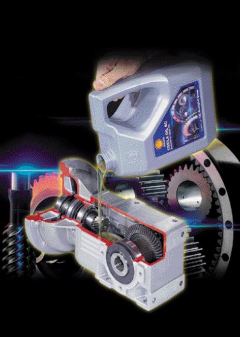
LUBRICATION
Before start-up, make sure the speed reducer matches the configuration for the mounting position specified on order, i.e. that the fill, drain and level plugs are located in the proper positions.
Except for life-lubricated gear units, it is normally advisable to double-check the lubricant charge. Oil level should reach the sight glass. When filling oil, keep to the manufacturer’s specifications as to oil type, viscosity and any additives. Do not forget that both ambient temperature and duty cycle play a role in the selection of optimal viscosity.
Bonfiglioli recommends synthetic oil over mineral oil. Though a bit more expensive, synthetic oils allow for extended change intervals, up to three times as long as mineral oils. In addition, their higher viscosity rating keeps properties unaltered in a broader range of ambient temperatures. Mineral and synthetic oils must not be mixed any under circumstances.
VENTILATION SYSTEM
Keep the reducer away from heat to minimize thermal radiation. If necessary, install suitable guards or a forced ventilation system. The fan cowl of the electric motor should never be obstructed and should be kept clean from accumulation of dust. When installing a gear unit, allow enough free space around the unit to ensure effective, natural air flow as well as to facilitate routine maintenance according to manufacturer’s instructions.
OTHER TIPS
In some cases the speed reducer is paint coated to customer requirements. When this is the case, be sure to avoid spilling solvents on rubber oil seals. Protect oil seals with rubber tape or grease. Do the same with drain or level plugs as well as the name plate.
Whenever a reducer has been partially or fully disassembled in order to perform maintenance operations, replace gasket and oil seals with new ones, as they are likely to be damaged in the process. Be sure to have the required spare parts available, and use original spares only.
Print this page