News
TUNING UP YOUR CLEANER SYSTEM FOR maximum performance
February 1, 2000 By Pulp & Paper Canada
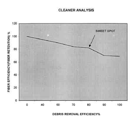 FIG 1. Typical debris removal efficiency and fibre retention efficiency for SC-A paper machine cleaners.
 Centrifugal cleaners can be marvelously effective, and in many situations indispensable in the stock preparation process. They can be compared (for those who remember) to the steam locomotive — highl…
Centrifugal cleaners can be marvelously effective, and in many situations indispensable in the stock preparation process. They can be compared (for those who remember) to the steam locomotive — highly productive and effective. However, they must be maintained regularly, adjusted properly and occasionally given a complete process tune up. Almost all cleaners can be made to produce some useful results — sometimes, unexpectedly good results.
There is a basic principle, which, it would seem, should apply to all equipment in a mill and, in the case of centrifugal cleaners, is especially vital. That is, a logical management approach to ensure correct application and then a disciplined maintenance routine to ensure continued good results of the centrifugal cleaners are needed. This seems like a basic article of faith; however, while most equipment will continue to do a reasonable job despite a lot of neglect, a neglected cleaner system will soon be reduced to a useless waste of energy and space. Mills have been seen to actually remove potentially effective systems rather than bother to work with them because of a lack of an effective management approach and maintenance routine.
A cleaner strategy
A logical management approach is fundamental. The key steps are:
1. Identify all the systems in your mill, even simple chip wash sand cleaners, and define for each a system objective; i.e., small dirt and bark, on paper machines, classification in the TMP mill, ink and stickies in a deinking operation, or whatever.
2. Bring out (if you can still find it) the original specification for the system. Unfortunately, these days you may very well not even be able to find the original supplier. Make a checklist as follows: Design tonnage (be sure to define accepts, or feed etc.); Design operating consistency of each stage; Specified pressures and pressure drops; Design loss to sewer; Design efficiency; Hydraulic capacity per unit — this is tricky; Pump curves.
3. Carefully obtain carefully today’s numbers corresponding to the above items.
4. Make a comparison table of the above with actual figures for each item. An accompanying flow sheet with both sets of numbers is very useful. Table I is a typical and convenient type of table to work from to fill a calculation program and prepare a simple flow sheet. No specific units for flow and mass are suggested because the industry still commonly uses metric and traditional units.
5. Analyze the situation.
Assuming that the simple things have been done — i.e., all pressures have been set properly, cleaners unplugged, etc — yet efficiency is still poor while flow to the sewer still resembles thickener accepts, it’s time to regard the second major principle of cleaner operation. A cleaner system is designed to suit a certain maximum tonnage based on maximum consistency for best efficiency of the units composing the system.
Every cleaner, whether pressurized (feed accepts and rejects) or older in design, (gravity discharge rejects) has a “sweet spot” — that is, a setting of pressure drop, feed consistency, and rejects volume where efficiency of debris removal is highest combined with minimum loss of fibre. (This can be called fibre efficiency.) Remember, any unit, old or new, can be highly efficient; it is just that the totally pressurized units are far easier to adjust by modern DCS-type systems, less messy and more flexible vis–vis their installation requirements.
Also, older, high-pressure drop units have a much greater fibre loss (lower fibre efficiency) for high debris removal.
If you have enough of the old ones and you can run them at the right conditions (their sweet spot), you can save a fortune on new equipment.
Note: Lower cone surface — most older design cones have a totally smooth surface which contributes to high debris removal efficiency for short fibre mechanical pulp without unreasonable fibre loss unless temperatures are rather high as with some TMP pulps. Newer, pressurized cleaners typically have built in patterns such as vanes or steps which lower the thickening factor (less fibre to rejects), especially useful for long fibre furnishes such as bleached kraft, although somewhat less efficient than smooth cones on short fibre pulps
How to find the “sweet spot”? — There are two ways.
Short method: Raise or lower the feed consistency of the first stage (assuming there are two or more stages) and simply monitor accepts tonnage versus dirt removal and fibre loss. Different feed to accepts pressure drops can be run, keeping in mind that higher pressure drops tend to encourage fibre loss although with pressurized rejects, rejects volumes can be correspondingly reduced to control this without losing dirt removal effect (to a certain limit).
Note here that this discussion deals with making first stage adjustments. It is strongly recommended to keep subsequent stages always at optimum design settings of pressure drop and lower consistency according to original specs. Any subsequent cascaded stage, i.e., a second, third or fourth stage typically acts to recover fibre and send it back to the first stage without interrupting rejects flows and accumulating dirt, so as to let these stages run “easy”. Optimize the first stage first and debug the other stages later if need be.
Long method: This is more scientific but requires much more time, set-up, and a patient testing department, unless reliable flow, consistency and possibly, on-line debris testing are in place. An individual cleaner unit identical to those used in the first stage (and the other stages if you get that far) is set up in parallel with the operating stage by tapping off the main feed header and equipping it with feed and accepts valves to allow different pressure levels. Accepts and rejects flows are directed to a barrel and bucket or whatever. The time to fill these receptacles is monitored to allow the establishment of total feed flow (total feed flow = accepts + rejects flows) for a given feed to accepts pressure drop (and rejects pressure if applicable). For these sets of conditions, consistencies and debris removal are calculated along with reject rates by mass and volume for each set of samples. These data will give the “sweet spot” and all the parameters needed to develop a flow sheet and size of a system, which will perform well. For example, a sample table can be set up as shown.
These are typical figures for an SC-A paper machine application for a fully pressurized cleaner whose reject rate is lowered by increasing reject pressure. A gravity discharge unit would require varying accepts pressure or, for large changes, varying reject tip size. Every grade will have its peculiarities, with less fibre loss for mechanical grades, for example. For the example cited, the best running spot for least fibre loss and best efficiency (sweet spot ) was at a rejects pressure of 6 psi. At lower rejects pressure, fibre loss increased (lower fibre efficiency) but dirt removal efficiency increased very slightly.
One could try other (accepts – feed) pressure drops with the same feed consistency or the same pressure drop and lower or higher consistency, but stay with the supplier’s original design feed consistency as a base line unless the current operation will not allow this. In other words, if recommended design is 0.65% and the mill has to run at 0.85% due to tonnage and thickener capacity restraints, test at the consistency available. If you have time, try to run at a lower consistency when production demands will permit less feed tonnage and hence lower consistency to get your comparison numbers. (This may be well worth doing.)
The test unit can be set up in parallel with the other stages to reasonably replicate the best running conditions for all stages. This should be done, noting that with each subsequent stage, feed concentration contains more debris by percent, thus feed consistency likely will be lower and reject rates higher to get the best results and separate good fibre from rejects. If it is not possible to test t
he other stages, use data for first stage and allow a few points drop in feed consistency and rise in reject rate by mass in volume at the same pressure drop, but always err on the side of conservatism. Being conservative means that you should assume that due to the rise in concentration of rejects in feed and rejects flow and the increasing fibre length and stiffness as evidenced by rising freeness at progressively lower stages, you also assume the rejects rates to be a bit higher and feed consistency to be a bit lower than may be needed. Thus, you will ensure that the system will be successful.
A cleaner system, that is too big will always do a good job; one that is too small never will.
How the sweet spot is established: Optimum pressure drop, reject rates, and flow per unit are known. You know how many cleaners you have for each stage; multiply this number by the flow per unit you found for the best conditions. Fit this into a new trial flow sheet; i.e., flow, consistency, and rejects rate by flow and volume are plugged in. (It is assumed you have a decent flexible calculation program such as Massbal.) Solve for the accepts tonnage your system will produce, at the acceptable debris efficiency and fibre loss levels.
If you set up your system to the same parameters of feed consistency and mass/volume reject rates you found by trial, the system will replicate the results for that tonnage. If you want more tonnage, plug in the same parameters, but now input tons instead of flow and divide the found total flow by the flow per cleaner you found by testing. If you need more units per stage, install them. If you need less, blank some off, but again, remember to be conservative, a little bigger is always better for cleaner systems if you have the pump and thickener capacity.
Figure 1 shows how a typical cleaner on an SC-A paper machine application will run. The important point to make about the “sweet spot” noted on the curve is that the cleaners can be pushed to higher efficiency by increasing reject rates or increasing the feed to accepts pressure drop. However, the additional loss of fibre from the first stage will have to be accommodated by a larger cleaner system in stages two, three and four, etc. Failure to account for this will likely mean more loss of good fibre and a lower cleaning efficiency.
This brings about another subject that must be addressed in getting the most out of your cleaners.
Bottlenecks
There are three serious bottlenecks that commonly plague cleaner systems: pumps, thickeners, and air.
Thickening: Several modern systems have been designed with all the best control strategies and lay-out possible but they became boat anchors before the first start-up because the mill decided to save money on thickeners. The thickeners are there to serve the cleaners, not the reverse.
Pump capacity: Inadequate pump capacity should never occur but it does. Look at the flow and pressure levels you’re testing. If the flow sheet you developed says you need to install enough “pump” to do this, nothing else will suffice. If you aren’t confident in how to size the pumps get help. It is well worth the trouble to ask.
Air: Air in stock could be the subject of a separate article, but at least the basics of its effects on centrifugal cleaners have to be mentioned. A small amount of air in the stock has a definite helpful effect on a cleaner’s ability to separate debris from acceptable fibre, but this is limited to 0.05% or less. Anything more is a problem for the following reasons.
1. A cleaner that is too involved handling air will do much less cleaning.
2. If the air is accepted, the ramifications are obvious downstream: the sheet on a paper machine will have formation problems or, in a pulp mill situation where accepts are thickened, the thickener will lose capacity, cleaner consistency will be higher than it should be and, of course, efficiency will be reduced.
3. Some cleaners, due to internal pressure balance (much more pronounced with pressurized units) will reject excess air. This is a useful form of deaeration to a point but, as stated before, too much of this activity detracts from cleaning effort. Another serious consequence is that air rejected will start to accumulate in the lower stages, binding the pumps and must be removed by the installation of standpipes on the suction of at least one feed pump; i.e., of stage two or three.
Probably the best scenario is to be sure that no excess entrained air is present either in the raw stock, in the paper machine white water loop or the thickener white water loop in the case of pulp mill cleaning. The key is to ensure that the white water chest supplying the cleaner feed pumps has a downward velocity of 0.5 ft per second or slower. This allows air to naturally remove itself, by bubbling to the surface of the tank, instead of being drawn with the white water flow down into the suction of the pumps.
Fibre recovery –the final frontier
Once the system is set up for optimum conditions, there still may be room to recover fibre. One half tonne per day for 365 days per year can add up to a small fortune especially for bleached fine paper grades. There are two basic strategies:
1. Make small changes at a time. Try simply slightly reducing the reject rate on the first stage. Often, you can get away with this more easily for certain less sensitive grades of product or at certain times of the year, for example, in summer for bleached kraft when there are many fewer bark specks, small dirt and schlereids. Operators can simply run at different reject rates according to grade and/or feed dirt levels.
2. Fibre recovery equipment: This strategy allows you to leave the basic cleaner stages at their optimum settings but allows slightly lower fibre efficiency per stage and still accomplishes significant fibre savings. There are several units that are effective, but again, be conservative in your expectations and convince the supplier to be conservative. If the device comes at all close to expectations, it will save you a bundle. Also, remember that these units are handling concentrated dirt often with a lot of abrasives mixed in the fibre you want to separate. Thus, they may wear significantly. It is worth the investment to maintain them carefully.
Operator training: Never overlook this part of getting the best out of your cleaners now that you have made all the technical changes and spent money on improvements.
Ask the typical operator how the cleaners work and why you ask him or her to stick to the settings you have laid out and there is a very good possibility that most will have little real idea.
The amount of basic knowledge the floor operators need to know to improve their ability to adjust, run and have a feel for the cleaners is really not so great, just the simple principles discussed regarding pressure drops consistency and stable operation. A one-hour session well presented and attended per year is enough for mill crews. They will learn to think about what they are doing and will ask appropriate questions day to day. This is vital in keeping the system running at its best.
Maintenance: The obvious things to do such as repairing leaking hoses and O-rings or replacing cracked cones and sight glasses require no explanation (especially if the mill manager walks by the area regularly). The more subtle items may show no outward evidence of trouble, but problems may be present to a degree as to seriously degrade performance of the system. These items are: feed accepts or rejects orifice wear; internal head wear; internal cone wear.
Effects detrimental to the system for each of the above are:
Feed, accepts, rejects orifice wear: Wear of only one sixteenth of an inch on the accepts orifice for example will possibly increase feed capacity up to 10% which will mean more volume accepts and less percentage of rejects flow, possibly allowing an increase in dirt acceptance. This can be adjusted by increasing rejects rate by the means referred to before. But, the total increase
d flow induced by the larger accepts may mean the feed pump cannot supply this flow at a high enough pressure, thus feed to accepts pressure drop is reduced and the optimum required centrifugal force is lost, thus efficiency goes down.
Internal head wear: Effects of wear on the inside of the head can lead to subtle capacity increase as described above and of course unexpected mechanical failure can appear if the head gets too thin.
Internal lower cone (or reject tip wear): Turbulence or flow changes may occur with effects as above on efficiency; however, with cones which have a modified surface for thickening factor control (vanes, steps or similar), wear and smoothening of these surfaces will definitely cause thickening factor to rise significantly. Fibre loss increases, perhaps dramatically for hot stock, and feed consistency rises in the lower stages, thus compounding the loss of fibre, lowering efficiency, and causing a steady accumulation of debris in the system. Many cleaner systems for which all the correct settings have been maintained carefully have become poor performers because regular inspection and repair of internal surfaces was overlooked.
Summary
| If followed, the steps to analyze and tune up a cleaner system as described will definitely yield satisfactory results. There are, as with any equipment or system, more complicated means of approach, but in most cases these are not necessary, and most systems can be greatly improved without bringing in expensive outside help. It should be noted that reverse cleaner systems should be studied and treated in exactly the same way as forward systems; just be sure to study the original flow diagram for the system carefully. Reject rates and other parameters are calculated in the same way, just that rejects and accepts are reversed for each individual unit. A few forward designs have lightweights rejects takeoffs on the head. Again, the treatment is the same, just be sure to include these as rejects on your balance program. | P&PC |
Richard Price has many years of experience in the sales and service of cleaners. He is based in Foster, QC.
| * | Test 1 | Test 2 | Test 3 | Test 4 | |||||
| Consistency feed, % | 0.7 | 0.7 | 0.7 | 0.7 | |||||
| Consistency accepts, % | 0.68 | 0.65 | 0.62 | 0.6 | Consistency rejects, % | 1.1 | 1.2 | 1.4 | 1.9 |
| Press drop feed-accepts, psi | 25 | 25 | 25 | 25 | |||||
| Press rejects, psi | 8 | 7 | 6 | 5 | |||||
| Reject rate mass, % | 22 | 23 | 24 | 27 | |||||
| Reject rate vol, % | 10 | 10.5 | 11.5 | 13 | |||||
| Eff’y dirt, % | 75 | 80 | 85 | 86 | |||||
| Eff’y fibre, % | 90 | 90 | 85 | 75 |
| Stage 1 | Stage 2 | Stage 3 | Stage 4 | Stage 5 |
| Design | Design | Design | Design | Design |
| (actual) | (actual) | (actual) | (actual) | (actual) |
Press feed
Press accepts
Press rejects
Press drop
(feed-accepts)
Press diff
(accepts-rejects)
Consistency feed %
Consistency accepts %
Consistency rejects %
Reject wt by mass %
Reject wt by vol %
Pump (kw or hp)
System efficiency %
System fiber loss
Flow per cleaner (estimated)
Flow per cleaner (tested)
Print this page